Qanat Works engineering team · Last updated: October 2026
Contents
What is legacy drawing conversion?
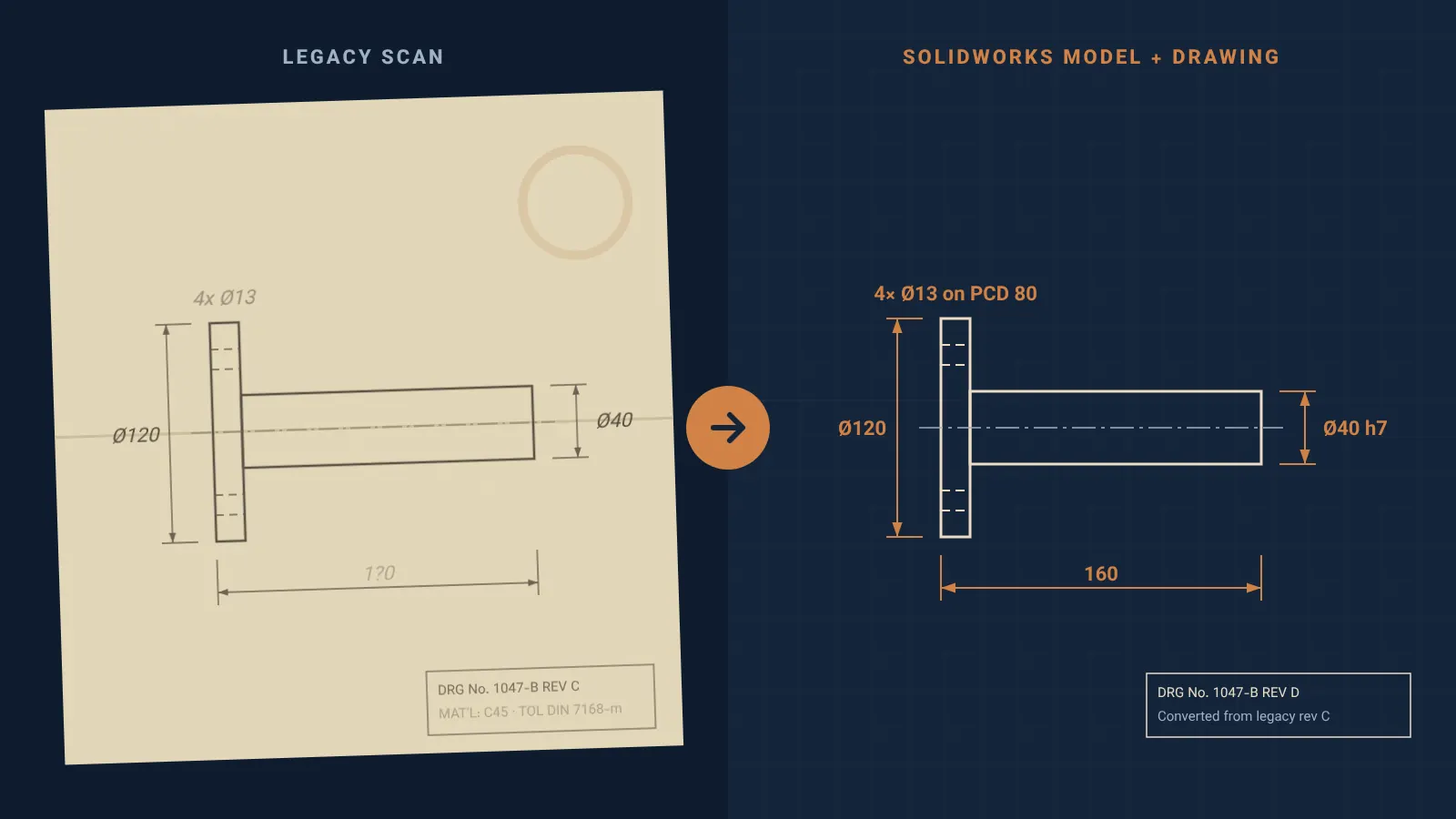
Legacy drawing conversion turns old engineering drawings into editable CAD data, such as SolidWorks 3D models and new 2D drawings. The originals can be paper prints, scans, PDFs or 2D DWG files. Each part is rebuilt from its stated dimensions. A new drawing is then created that keeps the original part number, revision, tolerances and notes. The result can be revised, exported to STEP or DXF, and sent to a supplier.
This guide is for maintenance teams, fabricators and engineering offices that still depend on paper prints, scanned archives or flat PDFs. It covers what to send, what can go wrong and how to judge the result.
How to convert legacy drawings to SolidWorks in 7 steps
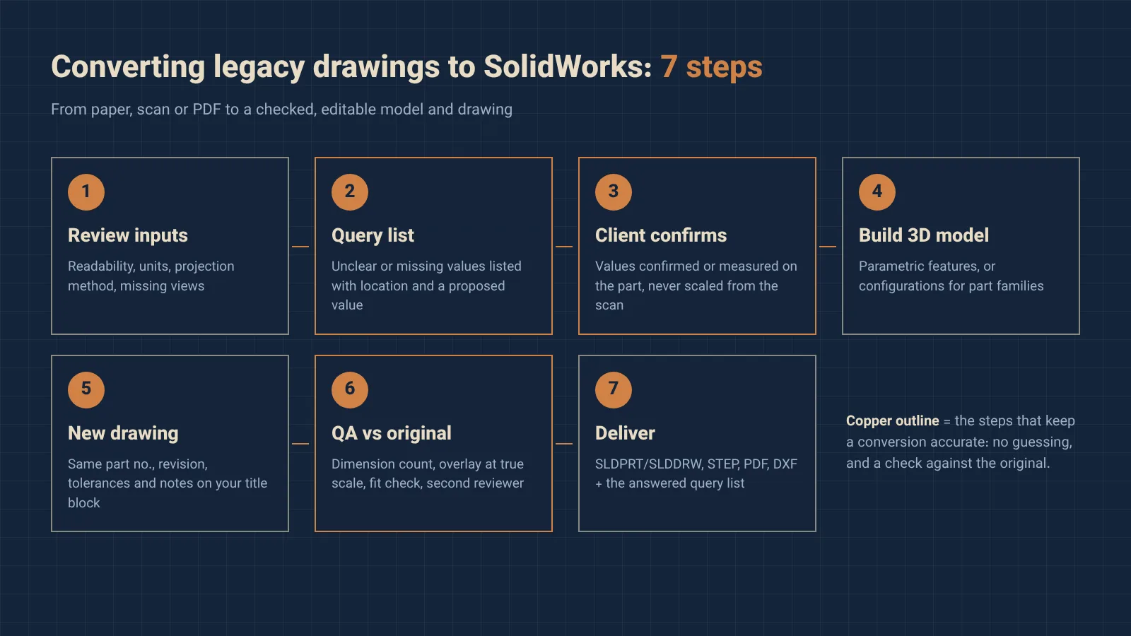
- Review the inputs. Check every sheet for readability, units, projection method and missing views.
- Write a query list. List each unreadable, missing or conflicting dimension with its location and a proposed value.
- Get answers from the client. Values are confirmed or measured on the physical part, never scaled from the scan.
- Build the 3D model. Model the part feature by feature from the confirmed dimensions, as a parametric model or as configurations for part families.
- Create the new drawing. Reproduce views, dimensions, tolerances and notes on the client’s title block, keeping the part number and revision.
- Check against the original. Count the dimensions, overlay the scan at true scale, check fits in assemblies and run a second-person review.
- Deliver and archive. Send native files, STEP, PDF and DXF where needed, together with the answered query list.
The sections below explain each step in more detail.
Why convert legacy drawings at all?
You convert legacy drawings because a scanned drawing is only an image. You can print it, but you cannot:
- send it to a laser cutter or CNC programmer as geometry,
- check whether a modified part still fits its mating parts,
- produce a DXF, a STEP file or an updated BOM from it,
- revise it cleanly when a dimension or material changes.
Most projects start with a concrete trigger. A spare part has to be remade and the supplier asks for a STEP file. A machine is being modified. Or the drawing archive is moving into a PDM system. Converting the drawings you actually need, in a sensible order, is usually better than converting a whole archive at once.
Which input formats can be converted?
Any readable engineering drawing can be converted, but the effort depends heavily on the input. In rough order from easiest to hardest:
| Input | What it really is | Typical issues |
|---|---|---|
| DWG / DXF (2D CAD) | Vector geometry with dimensions | Messy layers and blocks, but the geometry is usable as a reference |
| Vector PDF (exported from CAD) | Lines and text stored as vectors | Can be imported for reference; dimensions still need checking |
| Clean scan (300 dpi or better) | A raster image | Everything is redrawn; readable text keeps it straightforward |
| Poor scan, photocopy or fax | A degraded raster image | Faded numbers, cropped edges, distorted scale |
| Hand sketch with dimensions | Design intent, partially stated | Missing views, implied features, mixed units |
Can a scan be converted automatically? Not to manufacturing quality. Raster-to-vector tracing produces lines without design intent, and it can misread digits. A “3” read as an “8” is a scrapped part. In a manufacturing-grade conversion, a person reads every dimension and rebuilds the geometry from it.
How should missing or illegible dimensions be handled?
Missing or illegible dimensions should be listed and confirmed with the client. They should never be guessed or scaled from the scan. Old drawings often contain:
- dimensions that are unreadable or cut off at the edge of the scan,
- dimension chains that do not add up,
- features shown in one view but never dimensioned,
- notes that refer to standards or in-house specifications nobody has anymore.
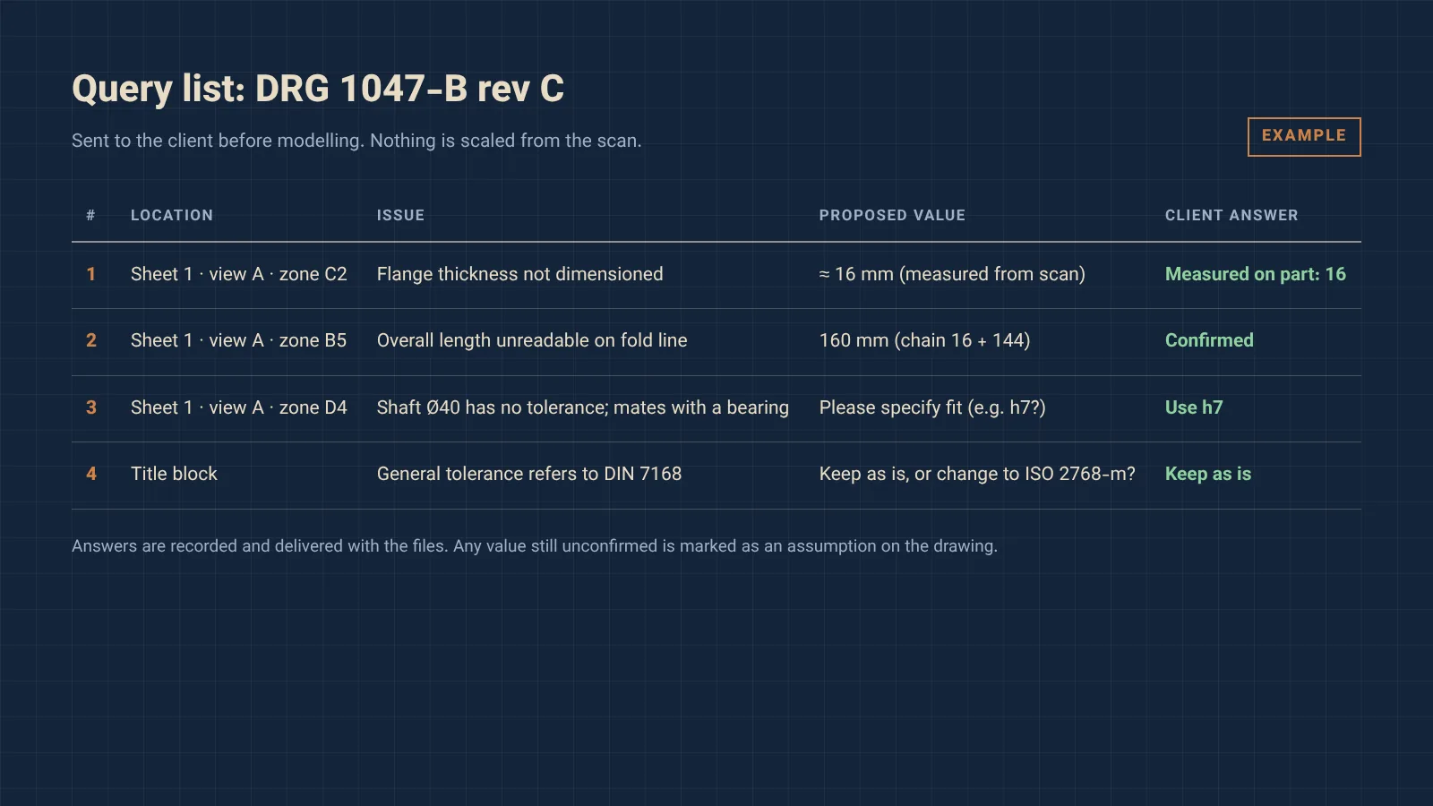
A scan can be distorted by a few percent without anyone noticing, so a dimension measured from it may look plausible and still be wrong. Each unclear item therefore goes onto a short query list:
- What is unclear: “Flange thickness on view A is not dimensioned.”
- Where it is: sheet, view and grid zone.
- Proposed value: “Measured from the scan ≈ 16 mm. Please confirm or measure the physical part.”
The client confirms, corrects or measures, and only then is the value used. If a value has to stay an assumption, it is marked on the new drawing so that nobody mistakes it for verified data.
Parametric model or “dumb” solid: which one do you need?
You need a parametric model if the part will ever be modified. A dumb solid is enough for reference only.
- Parametric (feature-based) model. The part is built from sketches and features, so changing one dimension updates the model and the drawing. Choose this for parts that will be modified, part families or a PDM system.
- Dumb solid. This is geometry without a feature tree, as you get from a STEP import. It is fine for clearance checks or as a mating part in an assembly, but not for future design changes.
Old “tabulated” drawings, with one sheet and a table of sizes, can often be replaced by a single model whose sizes are driven by a SolidWorks design table. Each row of the table becomes a configuration, which keeps a whole part family in one file.
What must be preserved from the original drawing?
A converted drawing must stay traceable to the original. At minimum it should keep:
- Drawing number and revision. The new file becomes a new revision, or keeps the number with a note that it was converted from the legacy original, according to your document control rules.
- Material, heat treatment and surface treatment notes.
- Tolerances exactly as stated, including the general tolerance note.
- Projection method. Older European drawings are usually first-angle (ISO). Mixing this up mirrors the views.
- Units. Inch drawings stay in inches unless metric conversion is explicitly requested.
Older drawings sometimes use superseded notation. Examples are surface-texture triangles from older DIN practice, or general tolerances that refer to DIN 7168, which was later superseded by ISO 2768. This notation can be translated into current standards, but only on request and with every change listed. Replacing a tolerance class or a surface specification is an engineering decision, and it belongs to the client.
How is a converted drawing checked before delivery?
A converted drawing is checked by comparing it with the original, dimension by dimension. A practical QA routine for each drawing:
- Dimension count. Every dimension and note on the original appears on the new drawing, or is listed with a reason.
- Overlay check. The scan is placed at true scale behind the drawing views to catch gross errors, such as a mirrored feature or a missing slot.
- Fit check. In assemblies, mating parts are put together to confirm that holes line up and that shafts fit their bores.
- Second-person review. Someone who did not model the part checks it against the original.
- File hygiene. File names are consistent, and custom properties (part number, revision, material, description) are set so that title blocks and BOMs fill in automatically.
For batches, agree on conventions first: file naming, title block, line standards and how assumptions are marked. Then approve a pilot of five to ten drawings before the full batch is converted.
What deliverables should you ask for?
Ask for the native files, a neutral 3D format and a PDF drawing. Typical deliverables for each part:
- SolidWorks part and drawing (
.SLDPRT,.SLDDRW) - STEP (AP214 or AP242) for suppliers and for other CAD systems
- PDF of the drawing for the shop floor and for approval
- DXF or DWG for sheet metal flat patterns or 2D-only workflows
- The answered query list, as a record of every decision
If you do not use SolidWorks yourself, STEP plus PDF is usually enough. The native files can still be archived.
What drives the cost of legacy drawing conversion?
The cost of legacy drawing conversion is driven mainly by part complexity, input quality and missing information. The full list:
- Part complexity: number of features, views and sections.
- Input quality: a clean vector PDF versus a faded photocopy.
- Missing information: each query takes time on both sides.
- 3D or 2D only: redrawing a 2D drawing is faster than building a model and a new drawing.
- Standards work: adding or modernising GD&T, or switching to your title block.
- Assemblies: fit checks, BOMs and exploded views.
- Batch size: repeated parts and part families cost less per drawing.
To get a reliable fixed price, send a representative sample: a few simple drawings, a few typical ones and the worst one. For larger batches, converting one sample drawing first lets you check the result before committing to the rest.
What to send for a quote
- Scans or PDFs of the drawings (300 dpi or better, the full sheet including the title block)
- The number of drawings, and which ones belong to assemblies
- The deliverables you need: native SolidWorks, STEP, PDF, DXF
- Your title block or drawing template, if you have one
- The units and drawing standard to keep (for example ISO, first-angle)
- Whether tolerances and notation stay as they are or should be modernised
- Your deadline, and whether you want a pilot batch first
- Your NDA, if you need one before sharing files
Frequently asked questions
Can a PDF drawing be converted to SolidWorks automatically?
No, not to manufacturing quality. A vector PDF can be imported as 2D reference geometry, but a usable 3D model still has to be built feature by feature. For raster scans, automatic tracing is not accurate enough for manufacturing.
What happens if a dimension on the old drawing is missing?
It goes onto a query list with its location and, where possible, a proposed value. The client confirms the value or measures the physical part. Nothing is guessed silently, and any remaining assumption is marked on the new drawing.
Will the tolerances be changed to current ISO standards?
Only if you ask for it. By default, tolerances and notes are reproduced exactly as stated. Modernisation is a separate option, and every change is listed for your approval.
Is the conversion useful if we don’t use SolidWorks?
Yes. STEP files open in practically every CAD system, and PDF and DXF cover the shop floor and cutting machines. The native files can be archived for later.
How are confidential drawings handled?
An NDA is signed before any files are shared. The files are used only for your project and are not reused or published.
Planning to convert legacy drawings to SolidWorks? Have a stack of old drawings? Send a representative sample (simple, typical and worst case). We will reply with a fixed price, a delivery date and a list of any questions.